Script Creation
There are various means of creating the required script code, in either of the discussed formats, all of which are designed to make it as simple as possible for the end user. Each will be discussed further in the coming chapters.
When creating scripts, you need to consider more than just the method of which the code is generated. You should take a step back and consider also the structure of your whole project. You will very quickly come to understand whether you would benefit from creating and using procedures, variables or even the use of, for example, a 'Procedure Library' (a central script containing a list of globally shared snippets of reusable code).
Your script design and project structure can be quite fluid and develop over time, so do not worry about getting it exactly right from the outset.
Recorder
The script recorder is a GUI feature which allows to record user interaction with the connected System Under Automation (SUA) into the active script. It will monitor and record all mouse & keyboard events.
As it always produces code into the active editor (the visible one), be sure to set the caret (cursor) position in the editor to the line you want the code to be inserted to. The recorder then converts mouse and key actions from the desktop viewer to Mouse, Press, Type and Typeline commands and inserts them into the editor. It also measures time spans between individual events, multiplies them by the configured coefficient and inserts them into the command through the wait parameters. Recorder behaviour may be customized through the Scripting->Script Recorder preference group in the Preferences window.
Having the Record & Replay feature doesn't mean that you just record something and the automation is finished. However it definitely makes your life much easier and considerably flattens the learning curve.
It will help you to create the basic flow of key and mouse events needed to reproduce a task or scenario on the connected environment. It is sometimes necessary to perform manual adjustments to the generated code, such as to modify timeouts, merge commands, add verification points, create reusable procedures or parameterise command arguments through variables where appropriate.
The recorder is easily accessible from the Ribbon bar:![]()
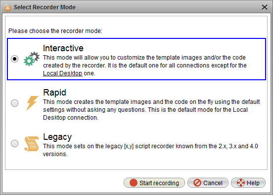
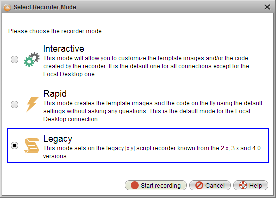
Once activated the recorder gives you the choice of three different operating modes. We will discuss each mode in turn throughout the following chapters.
- Interactive Mode
- Rapid Mode
- Legacy Mode
Interactive Mode
This mode gives the user great control at every stage of the recording process. Following each action performed against the live environment the user is able to define the exact commands and parameters that they wish to produce – all achieved through simple dialogs.
NOTE: This recording mode is not available when using the "Local Desktop" connection.
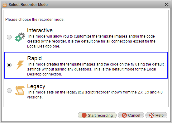
Once the Recorder has been activated it will invoke the recorder mode selection window providing the three options already mentioned. For this section we will continue with the first, "Interactive", mode:
Once the recorder has been initiated it will then react to every mouse action you perform within the Desktop Viewer window or on your keyboard (as long as your mouse is over the Desktop Viewer to give it focus).
Keyboard actions will be posted directly to the script editor with no interaction required.
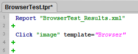
When performing a mouse action, i.e. Click, the first thing that Robot does is to analyze the current display:
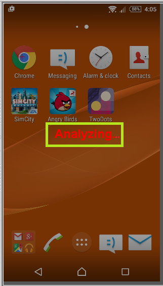
The purpose of this analysis is to allow Robot to determine the best image template(s) to create. It does so using a complex algorithm to ascertain the best crop section which follows the standard best practises for template creation; keep as small as possible/needed while remaining unique. Remember also that the image template doesn't always necessarily need to have any meaning in its own right.
For further guidelines on best practices please see our general help text and online tutorial.
Once Robot has completed this task internally it will present the suggested crop area along with some controls to customize the action further.
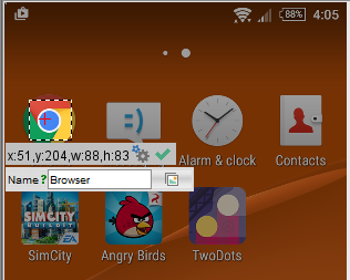
Along with details of the size and location of the cropped selection you will also see a few options, as follows:
| Confirm the selected area and the click point are correct and continue. |
| Customize the resulting action based on the current selection. (Explained further below) |
"Name" | This is the name you wish to give to the auto-generated Image Collection. |
| Existing Collections. Select this if you wish to append the new template to an existing image collection. |
To explain each of these options a little further
Confirm:
Once you have confirmed the desired action Robot will proceed to apply the action to the SUT, create the Image Collection/template and also insert the required script command into the active editor.
Customize:
If you select to customize the action you will be presented with three sub options:
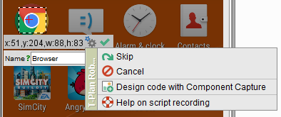
- Skip – Will apply the click action into the SUT without recording it to your script.
- Cancel – Will discard the action completely. It will not be applied to the connected environment, nor will it generate any code within your script.
- Design code with Component Capture – as it suggests, this will invoke the Component Capture wizard allowing you to customize the action that you wish to be recorded into your script.
(For more details on this option please see the Component Capture section of the online documentation.)
Name:
When entering the name manually, should it match an existing collections name the field will be highlighted yellow.
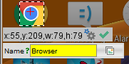
The collection name can be entered as a single value or as a folder path using the standard OS path separator. For example in Windows you could enter "Apps\Web\Browser\".
For instances where any folder does not already exist, it will be created otherwise it will be appended at the point of the lowest level existing folder.
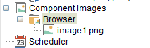
Existing Collections:
Selecting the existing collections button will open a small dialog presenting the "Component Images" tree. This allows you to browse all available collections in which to add your new template images.
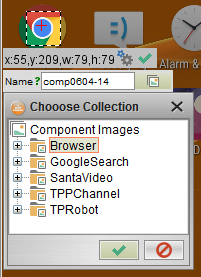
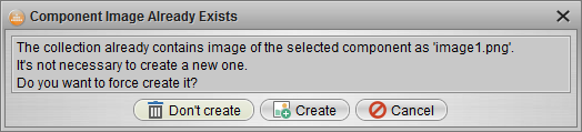
Should you manually enter or select an existing collection that already contains a similar image template you will be asked to confirm whether or not you still wish to create the new template.
You will notice that any keyboard actions applied during the recording process do not invoke any interactive dialogs; instead Robot immediately inserts the relevant script commands into the active editor. Additionally, Robot will insert a "wait" parameter in any command immediately prior to the "Type" or "Press" command.
TIP: When applying keyboard actions ensure the mouse pointer remains within the bounds of the Desktop Viewer window in order that the SUT retains the focus and therefore also remains the target of the action.
Rapid Mode
The 'Rapid' mode allows you to concentrate initially on the task at hand, which is to quickly and efficiently record the actions you perform against your System Under Automation such that they can then be replayed thereafter. It does so without interruption instead presenting you with the option to customize the recorded data upon completion.
Given the nature of automation on the "Local Desktop" this is the default recording mode when using this connection type. For this same reason the "interactive" mode is not available under the "Local Desktop" connection.
Once connected to your desired System Under Automation the recording is initiated in the standard ways, as listed previously.
Once "Rapid Mode" selection has been made you can immediately begin to perform the desired actions against the SUA.
As the name suggests there will be no interactions or popup dialogs presented by Robot, allowing you an uninterrupted session to record your actions.
TIP: When using the "Local Desktop" connection you must press RIGHT CTRL to end the recording session and return to the Robot UI.
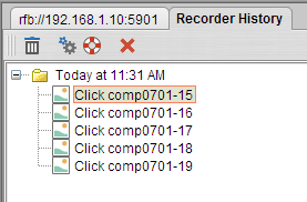
When you have completed your recording session Robot will display the "Recorder History" window in the right hand pane.
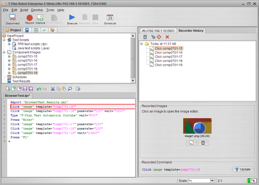
The Recorder History pane also links in with the script editor such that when a line of code is clicked it will not only be highlighted itself but will also display the related captured image(s). Similarly, selecting a captured image on the right will highlight the related line of code in the editor.
The Recorder History panel is presented in a tree view which contains a folder for each recording session performed within the current Robot session. Within each folder it will list each image collection that was generated during the recording.
Within the Rapid mode the image collections are automatically named based on the convention:
Click comp<mmdd>-<n>
The mini toolbar offers just a few options, namely the ability to Delete the selected image collection.
| Delete the currently selected image collection. |
| Quick access to the Script Recorder Preferences. |
| Open the Recorder feature Help text. |
| Close the Recorder History panel. |
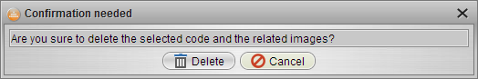
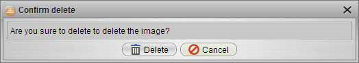
Upon selecting Delete, you will be asked to confirm this action before the data is permanently deleted.
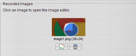
Below the image collection tree you will see a preview thumbnail of each image template that was automatically captured during the recording process for the currently selected collection. This may range from a single template, as below, to a number of templates.
If Robot detects that the clicked item can be displayed differently under certain states it may attempt to capture of these. For example, a button can have various states such as natural, hovered, pressed, etc.
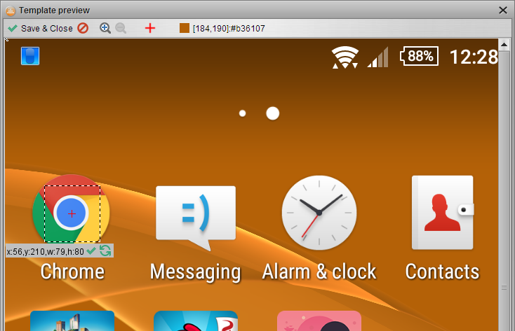
Although Robot captures these various image templates based on a complex intelligent algorithm they may require slight modification to ensure they are as you need. Changes can be made by clicking the image preview or selecting the "Edit" button:![]()
This will open the "Template Preview" window where you can adjust or reselect the desired template area. Here you can also set/reset the click point as required. Once complete select "Save & Close".
Similarly, you may find that Robot occasionally captures additional or unwanted template images. These can easily be removed from the collection by selecting the "Delete" button below the relevant template preview.![]()
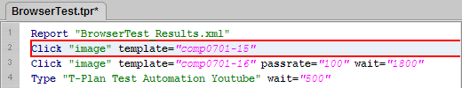
Finally, the bottom pane displays the actual script command that was generated by the recorder for the currently selected collection.
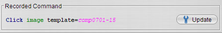
As always any generated code can be edited at any time directly in the script editor window, using any of the scripting aids and wizards. Additionally, the command can be edited from the context of the Recorder History window by selecting the "Update" button.![]()
This will invoke the properties for the command allowing you to adjust any parameters as required, including perhaps the search area, tolerance level ("passrate"), etc.
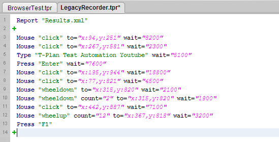
Legacy Mode
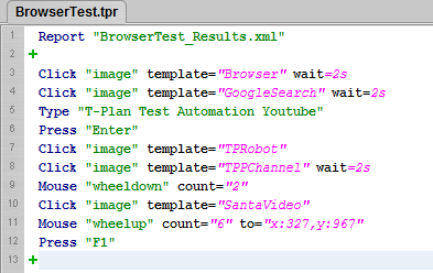
This mode reuses the pre 4.1 recoding mechanism. It records mouse and keyboards actions directly into the script editor with no interruptions or popup interactions. All mouse actions that are performed against the SUT during the recording generate script commands that are based on the mouse location using a coordinate approach.
This mode is generally used where the AUT is stable in terms of its layout and design.
Any changes that are required for the captured commands are achieved through the script editor window using he standard scripting aids and wizards.
As the "legacy" mode produces code based on the "Mouse", "Type" and "Press" commands there is no built in mechanism to 'wait' for something to occur, therefore, this mode also inserts a "Wait" parameter for each command thus recording and eventually executing your actions in real time.
Any required image/text comparisons, verification points or screenshots should be inserted after the recording and can be generated using the standard menus and scripting aids.
Component Capture Wizard
Component Capture helps the script developer generate an automated scripted action in a simple way. The feature was updated in the 4.0 release but the legacy 3.x functionality is still available.
- Component Capture v4 uses a wizard which creates the target action in three or four simple steps.
- Component Capture v3 uses a single screen dialog. This process is faster but is less user friendly, it exposes less action parameters and it is not intuitive for "search by color" and OCR actions.
Both the v4 wizard and the v3 dialog provide a button allowing to switch to the other version. This preference is remembered and the chosen capture version is then used for all action unless the user switches the versions again.
Component Capture gets activated through the  Capture tool bar button or the corresponding item of the Script menu.
Version 4
Selection of the ![]() Capture tool bar button opens the Component Capture Wizard. The first Action Type screen allows to choose the action type and subtype.
Capture tool bar button opens the Component Capture Wizard. The first Action Type screen allows to choose the action type and subtype.
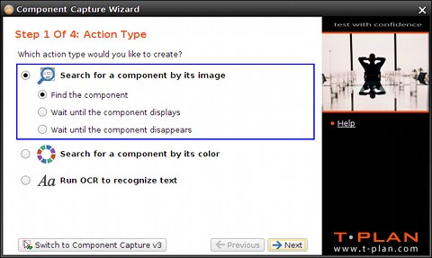
Supported types:
- Search for a component by its image creates an action based on the "search2" image comparison method. It looks for the component on the screen by its template image.
- Search for a component by its color searches for the component by the specified color, minimum and maximum sizes. It relies on the "object" image comparison method.
- Run OCR to recognize text will employ the OCR engine to identify the component by its text. It uses the "tocr" image comparison method.
The action subtype defines which image comparison command will be used to identify the component:
- The first "Find <subj>" subtype will generate a call of the Compareto command to perform one time comparison.
- The second "Wait until the <subj> displays" subtype will utilize the Waitfor match command to perform the comparison repeatedly until the component gets identified or the specified time out is reached.
- The second "Wait until the <subj> disappears" subtype will employ the Waitfor mismatch command to perform the comparison repeatedly until the component disappears from the screen or the specified time out is reached.
When the selected action requires a template image (such as the Search for a component by its image one) the wizard continues with the Component Image(s) screen. This screen may not be available when the image or images are already known, for example when the wizard gets opened for an existing image or image collection displayed in the Component Images branch of the Project View.
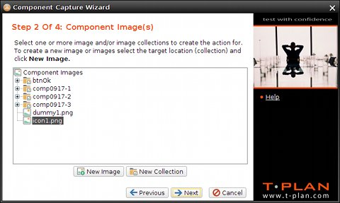
It supports a set of actions allowing to define the template image(s) and/or image collection(s) (folders) to be involved in the search. It's functionality is similar to the Component Images branch of the Project View:
- To create a new collection (image folder) click New Collection
- To create (crop) a new component image from the current desktop screen click New Image
- To continue select one or more images or image collections in the tree and choose Next
The next Parameters screen is dynamic and shows parameters of the selected action type and subtype (the selected comparison method and command):
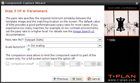
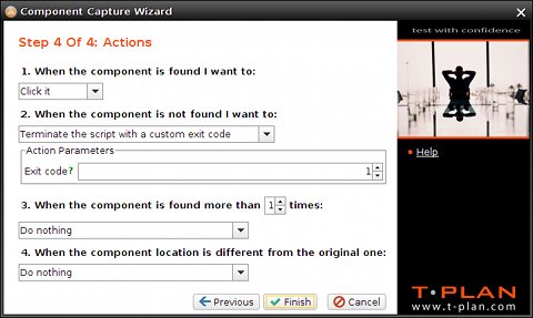
The final screen defines what to do with the identified component. There are multiple options allowing to click, right click or double click the component or make the action just verify the component existence. The screen also allows to define error handling such as what to do when the component is not found, there are multiple instances (match locations) on the screen or when the component location is different from the original one.
Version 3
Component Capture v3 is typically used to cut an image of a component (button, field, text, ...) from the current desktop image, save it to the project template folder and generate a piece of code working with the image into the active script editor. Though it can also be used for the "search by color" and OCR actions it requires the user to pass the initial cut area selection screen which is then used to limit the action to (so called "comparison area").
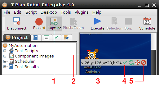
- To activate the Component Capture mode select the Component Capture button on the tool bar or the Tools->Component Capture menu item. The desktop image freezes and turns gray save for the default capture area. To cancel the capture mode simply click (deselect) the button or menu item again.
- To adjust the capture area drag its corners or dashed side lines. To move the area perform a mouse drag with either Ctrl, Alt or Shift pressed. It is recommended to create the component images as small as possible to improve performance and increase accuracy.
- The red cross located in the centre of the capture area is called click point. It can be also dragged and it defines where to click when the component is found on the screen. The click point may be even dragged out of the capture area to automate tasks such as "click XY points in this and this direction from the component".
- Once you are satisfied with the capture area and the click point location, select the OK button to proceed to the Component Capture window.
- While selecting you may cancel the current capture area through clicking on the red cross Cancel button. To recreate the area somewhere else simply drag your mouse in the image (move mouse while holding the left mouse button). To cancel the whole action click the rightmost Exit button.
The Component Capture window defines the target template image file and the task(s) to be carried out by the script:
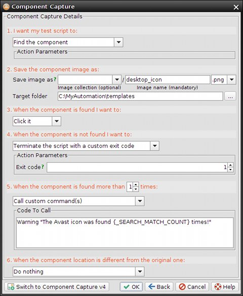
- The first group defines the task to be carried out with the selected area. It may be saved to a template image for the Image Search purposes or used as an area of interest for the OCR or Object Search. Some actions may have additional parameters which display dynamically below the drop down. For example, the "Wait until the component displays and click it" action has a configurable timeout.
- The second group of controls specifies collection, name and target folder for the component image file. It is not visible if the selected task is an OCR or object search one. The Image Collection field is optional and allows to create a new subfolder (collection) for the component images. The drop down is pre-populated with folders available in the target one. When the collection is defined, the image comparison will process all images in the specified directory (or its subdirectories). To read more about collections read the Image Collections chapter of the scripting language specification. The Image Name is mandatory and defines the image file name without extension. The format and extension is derived from the Extensions drop down next to the field. The Target Folder is by default set to the template directory defined by the TEMPLATE_DIR variable in the script. Images and collections residing under this directory will be called through a relative path. For example, the parameters displayed in the picture instruct the window to create a new component image desktop_icon.png under the _C:\MyAutomation\templates template path.
- The third group defines what is to be done when the task is successfully completed, that is when the component was found (image search tasks), when the OCR succeeded to recognize text in the target area and optionally match it against a pattern, or when at least one object of the specified color was found in the area. The most common actions are mouse clicks.
- The fourth group specifies what is to be done when the component is not found on the screen. Similar to the previous control group there's a drop down with a predefined set of actions. The action selected in the picture will make the script finish with an exit code of 1.
- The fifth group defines what to do when multiple instances of the component are found on the screen. The list of supported actions is similar to those available in the previous group. The action selected in the picture will call a custom Warning command which will create a warning note in the script report.
- The last group deals with the component location change. As the original coordinates of the component are saved in the image file meta data, the script allows to verify whether the component has moved and associate it with an action. The one selected in the picture will ignore any location changes.
To close the window, save the component (template) image and insert the corresponding script code into the active editor select the OK button. To go back to the previous desktop view with the capture area click Back. To cancel the window, discard any changes and switch off the Component Capture mode select Cancel. To open this help topic select Help.
For example, when closed with OK the window above inserts into the active editor:
WaitFor match template="desktop_icon.png" method=search2 timeout=20s
if ({_EXIT_CODE} > 0) {
   Exit 1
 } else if ("{_SEARCH_MATCH_COUNT}" > 1) {
   Warning "The Avast icon was found {_SEARCH_MATCH_COUNT} times!"
 } else {
   Mouse click to=x:{_COMPARETO_CLICK_X},y:{_COMPARETO_CLICK_Y}
 }
Manual Creation
The scripting aids discussed in the previous chapters are a good way to get your basic script flow started very quickly and easily. However, there are times when this can may need further 'tweaking' to open it up to the flexibility you may require, for example to include the use of Variables or to wrap some of the commonly reused sections into a single Procedure or simply removing/adjusting any wait values. For this we must start to work directly in the script editor.
Any and all of the code that is generated through any of the scripting aids can not only be created manually but it can also be manually edited thereafter.
Both the creation and modification of code can be achieved directly within the script editor window or through invoking the commands Properties dialog.
You will find that the best results come if you are comfortable first understanding a few of the scripting basics, such as:
- Scripts are processed line by line. A single command or expression cannot be split to multiple lines unless the specification explicitly says so.
- Lines may contain any number of leading and/or trailing white space characters, i.e. spaces, tabulators, etc. They will be trimmed before further processing.
- Empty lines are ignored.
- Lines beginning with hash '#' or double backslash '//' are considered to be comments and they are ignored.
- Other text lines which are not eliminated by the rules above should contain one element of the scripting language, such as a command, procedure header, procedure call, an if/else/for statement or its terminating right curly brace '}'.
Variables and Procedures
Variables can be used to substitute any parameter value elsewhere in the script. Given that Variables can be called also any number of times throughout a script(s) it also serves as a good way to minimize script maintenance, requiring just a single point of update.
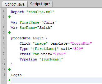
Using a basic example, below, we will take a brief section of recorded code and add some flexibility with the addition of Variables and a Procedure.
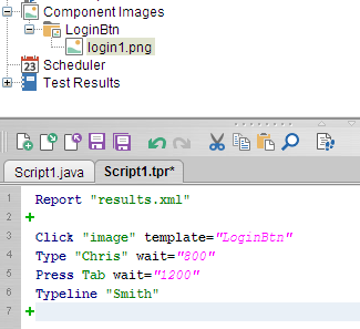
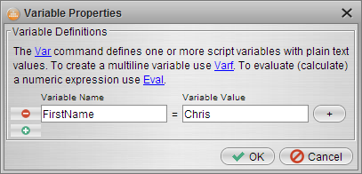
Firstly I can add a Variable that will replace the First Name entered in the first Type command. I can do this by manually typing "Var FirstName=Chris" or by selecting the Green "+" and finding Var in the command list to invoke the properties dialog:
NOTE: The variable must be declared prior to its use; in this case therefore it should be done prior to line 4.
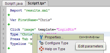
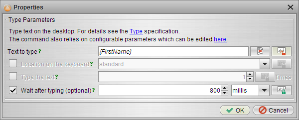
Next, we need to amend the Type command to pick up the new Variable value. Again this can be achieved by manually changing the text directly in the editor from "Chris" to "{FirstName}", or by right clicking the Type command and selecting Properties:
NOTE: When calling variables you must enclose the Variable name in curly braces:
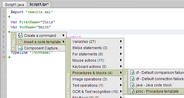
Having done the same with the Surname (the second Typeline command) we end up with code that allows us to just change the variable values very easily should we wish.
Now we can wrap this into a Procedure such that these 4 lines of code can be reused anywhere throughout our entire Project, just by calling the Procedure name.
A Procedure is defined by enclosing the required code between two curly braces, preceded by the Procedure command and the chosen name.
Using the green "+" menu, at the start of the code, select to insert a Procedure:
Insert the Procedure name as indicated and then move the action code (Ctrl+X then Ctrl+V) between the open and closing curly braces.
We can then call that code just by entering the Procedure name, i.e. "Login" (at Line 13):
NOTE: Procedures must be called after they have been defined. Remember that script execution is performed line by line unless otherwise determined by the script flow.
Boolean Expressions
Boolean expressions facilitate constructions like if/else and for. The following operators are supported:
- Parenthesis '(' and ')'
- Greater than '>' and lower than '<'. These two operators require numeric arguments.
- Equal to '==' and not equal to '!='. Arguments are first converted to numbers and compared. If at least one of the arguments is not a number, a plain string comparison is performed. Examples:
- Result of 'yes == no' will be false
- Result of 'yes != no' will be true
- Result of '1.0 == 1' will be true because both arguments can be converted to a number and the numeric values are equal.
- Operators '&&' and '||' - logical "and" and "or". These operators require Boolean arguments, i.e. other expressions. Example:
- Expression '1 > 0 || yes != no' will be true because one of the two expressions is true
- Expression '1 > 0 && yes != no' will be false because one expression is false
T-Plan Robot also supports a set of operators allowing to verify the existence of variables and compare strings:
- Unary operator 'exists <variableName>' verifies existence of a variable. Example:
- Expression 'exists _REPORT_FILE' will be true if the script creates a report through the Report command
- Operator 'contains' verifies whether the first string argument contains the other one (case sensitive). Example:
- Expression '"{_MACHINE}" contains "server"'will be true if the connected VNC server name contains 'server'
- Operator 'startswith' verifies whether the first string argument starts with the other one (case sensitive). Example:
- Expression '"{_DISPLAY}" startswith "localhost"'will be true if the connected VNC desktop name starts with 'localhost', for example 'localhost:1'.
- Operator 'endswith' verifies whether the first string argument ends with the other one (case sensitive). Example:
- Expression '"{_DISPLAY}" endswith ":3"'will be true if the connected VNC server runs on port 5903 (which is typically indicated by the ':3' display number in the desktop name).
- Operator 'matches' compares the first string argument to a java.util.regex.Pattern compliant regular expression. Example:
- Expression '"{_DATE}" matches "201508[12][1-5]"' will be true if the current date is between 11 and 15 or between 21 and 25 August 2015.
If/Else Statement
T-Plan Robot Enterprise supports if/else statements. The format is:
if (<boolean expression>) {
<commands>
} else if (<boolean expression>) {
<commands>
} else {
<commands>
}
The 'else if' and 'else' branches are optional. While the number of 'else if' branches is not limited, there can be just one 'else' construction. Note that the enclosing curly braces '{' and '}' must be on the same line as their associated if/else/else if keyword exactly as is displayed above. The right curly brace '}' terminating the whole structured block is the only exception and it must be alone on a single line. Example:
# Look for an image on the remote desktop
 Compareto "pattern.png" method="search"

 # Exit if the image is not found,
 if ({_EXIT_CODE} > 0) {
     Exit 1

 # If the image was found more times, take a screenshot and add a warning to the HTML report
 } else if ({_SEARCH_MATCH_COUNT} > 1) {
     Screenshot unexpected.png
     Warning "Unexpected behaviour - the template image was found {_SEARCH_MATCH_COUNT} times!" image=unexpected.png
 }
If/else statements can be nested and combined with other constructions like the for statement as is usual in any other structured programming language.
For Statement
T-Plan Robot Enterprise supports for statements which allows to iterate over a range of values or loop as long as a particular condition is satisfied. There are two general forms of the for statement.
1. Conditional for Statement
First variant of the for statement executes as long as the specified Boolean expression results true:
for (<statement1>; <boolean expression>; <statement2>) {
<commands> }
As the Boolean expression is being evaluated before every loop, the commands inside the loop will not be executed at all if the expression results false right from the beginning. Statements statement1 and statement2 are evaluated using the Eval command and should have a syntax like '<variable>=<numeric expression>'. They can be also empty.
The following examples are equivalent and loop for values of variable 'index' ranging from 0 to 5. Both code snippets will type '012345':
for (index=0; {index}<6; index={index}+1) {
     Type {index}
}
Eval index=0
for ( ; {index} < 6; ) {
     Type {index}
    Eval index={index}+1
}
Version 2.3 and newer also supports a simpler syntax where the variable calls inside the statement header omit the curly braces, such as for example:
for (index=0; index<6; index=index+1) {
}
2. For Statement Iterating over a Predefined Set of Values
This form allows to iterate over a predefined set of values:
for <variable name> in <list of space separated values> {
<commands>
}
The following example will type the sentence "I speak English, Spanish, Brazilian Portuguese."
Type "I speak "
for language in English Spanish "Brazilian Portuguese" {
      if ("{language}" == "Brazilian Portuguese") {
         Type "{language}."
     } else {
         Type "{language}, "
     }
}
The value set can be also specified by a variable. Version 3.0.1 and higher support values containing spaces specified through a variable. The following code shows the previous example with the value set specified through variables. Note that the variable call must NOT be enclosed with double quotes because it would be handled as a single value.
Type "I speak "
Var VALUES="English Spanish \"Brazilian Portuguese\""
for language in {VALUES} {
     if ("{language}" == "Brazilian Portuguese") {
         Type "{language}."
     } else {
         Type "{language}, "
     }
}